|
|
|
There is a direct relationship between the value of the Internet and the number of sites connected to the Internet. As the Internet grows, the value of each site's connection to the Internet increases because it provides the organization with access to an ever expanding user/customer population.
Internet Scaling Problems
Over the past few years, the Internet
has experienced two major scaling issues as it has struggled to provide
continuous and uninterrupted growth:
The first problem is concerned with the eventual depletion of the IP address space. The current version of IP, IP version 4 (IPv4), defines a 32-bit address which means that there are only 232 (4,294,967,296) IPv4 addresses available. This might seem like a large number of addresses, but as new markets open and a significant portion of the world's population becomes candidates for IP addresses, the finite number of IP addresses will eventually be exhausted.
The address shortage problem is aggravated by the fact that portions of the IP address space have not been efficiently allocated. Also, the traditional model of classful addressing does not allow the address space to be used to its maximum potential. The Address Lifetime Expectancy (ALE) Working Group of the IETF has expressed concerns that if the current address allocation policies are not modified, the Internet will experience a near to medium term exhaustion of its unallocated address pool. If the Internet's address supply problem is not solved, new users may be unable to connect to the global Internet!
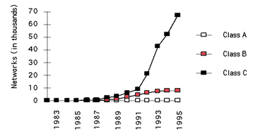
Figure 1: Assigned and Allocated Network Numbers
The second problem is caused by the rapid growth in the size of the Internet routing tables. Internet backbone routers are required to maintain complete routing information for the Internet. Over recent years, routing tables have experienced exponential growth as increasing numbers of organizations connect to the Internet - in December 1990 there were 2,190 routes, in December 1992 there were 8,500 routes, and in December 1995 there were 30,000+ routes.
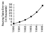
Figure 2: Growth of Internet Routing Tables
Unfortunately, the routing problem cannot be solved by simply installing more router memory and increasing the size of the routing tables. Other factors related to the capacity problem include the growing demand for CPU horsepower to compute routing table/topology changes, the increasingly dynamic nature of WWW connections and their effect on router forwarding caches, and the sheer volume of information that needs to be managed by people and machines. If the number of entries in the global routing table is allowed to increase without bounds, core routers will be forced to drop routes and portions of the Internet will become unreachable!
The long term solution to these problems can be found in the widespread deployment of IP Next Generation (IPng or IPv6) towards the turn of the century. However, while the Internet community waits for IPng, IPv4 will need to be patched and modified so that the Internet can continue to provide the universal connectivity we have come to expect. This patching process may cause a tremendous amount of pain and may alter some of our fundamental concepts about the Internet.
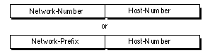
Figure 3: Two-Level Internet Address Structure
In recent years, the network-number field has been referred to as the "network-prefix" because the leading portion of each IP address identifies the network number. All hosts on a given network share the same network-prefix but must have a unique host-number. Similarly, any two hosts on different networks must have different network-prefixes but may have the same host-number.
Primary Address Classes
In order to provide the flexibility
required to support different size networks, the designers decided that
the IP address space should be divided into three different address
classes - Class A, Class B, and Class C. This is often referred to as
"classful" addressing because the address space is split into three
predefined classes, groupings, or categories. Each class fixes the
boundary between the network-prefix and the host-number at a different
point within the 32-bit address. The formats of the fundamental address
classes are illustrated in Figure 4.
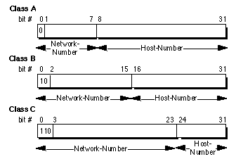
Figure 4: Principle Classful IP Address Formats
One of the fundamental features of classful IP addressing is that each address contains a self-encoding key that identifies the dividing point between the network-prefix and the host-number. For example, if the first two bits of an IP address are 1-0, the dividing point falls between the 15th and 16th bits. This simplified the routing system during the early years of the Internet because the original routing protocols did not supply a "deciphering key" or "mask" with each route to identify the length of the network-prefix.
Class A Networks (/8 Prefixes)
Each Class A network address has
an 8-bit network-prefix with the highest order bit set to 0 and a
seven-bit network number, followed by a 24-bit host-number. Today, it is
no longer considered 'modern' to refer to a Class A network. Class A
networks are now referred to as "/8s" (pronounced "slash eight" or just
"eights") since they have an 8-bit network-prefix.
A maximum of 126 (27 -2) /8 networks can be defined. The calculation requires that the 2 is subtracted because the /8 network 0.0.0.0 is reserved for use as the default route and the /8 network 127.0.0.0 (also written 127/8 or 127.0.0.0/8) has been reserved for the "loopback" function. Each /8 supports a maximum of 16,777,214 (224 -2) hosts per network. The host calculation requires that 2 is subtracted because the all-0s ("this network") and all-1s ("broadcast") host-numbers may not be assigned to individual hosts.
Since the /8 address block contains 231 (2,147,483,648 ) individual addresses and the IPv4 address space contains a maximum of 232 (4,294,967,296) addresses, the /8 address space is 50% of the total IPv4 unicast address space.
Class B Networks (/16 Prefixes)
Each Class B network address has
a 16-bit network-prefix with the two highest order bits set to 1-0 and a
14-bit network number, followed by a 16-bit host-number. Class B networks
are now referred to as"/16s" since they have a 16-bit network-prefix.
A maximum of 16,384 (214 ) /16 networks can be defined with up to 65,534 (216 -2) hosts per network. Since the entire /16 address block contains 230 (1,073,741,824) addresses, it represents 25% of the total IPv4 unicast address space.
Class C Networks (/24 Prefixes)
Each Class C network address has
a 24-bit network-prefix with the three highest order bits set to 1-1-0 and
a 21-bit network number, followed by an 8-bit host-number. Class C
networks are now referred to as "/24s" since they have a 24-bit
network-prefix.
A maximum of 2,097,152 (221 ) /24 networks can be defined with up to 254 (28 -2) hosts per network. Since the entire /24 address block contains 229 (536,870,912) addresses, it represents 12.5% (or 1/8th) of the total IPv4 unicast address space.
Other Classes
In addition to the three most popular classes,
there are two additional classes. Class D addresses have their leading
four-bits set to 1-1-1-0 and are used to support IP Multicasting. Class E
addresses have their leading four-bits set to 1-1-1-1 and are reserved for
experimental use.
Dotted-Decimal Notation
To make Internet addresses easier for
human users to read and write, IP addresses are often expressed as four
decimal numbers, each separated by a dot. This format is called
"dotted-decimal notation."
Dotted-decimal notation divides the 32-bit Internet address into four 8-bit (byte) fields and specifies the value of each field independently as a decimal number with the fields separated by dots. Figure 5 shows how a typical /16 (Class B) Internet address can be expressed in dotted decimal notation.
Figure 5: Dotted-Decimal Notation
Table 1 displays the range of dotted-decimal values that can be assigned to each of the three principle address classes. The "xxx" represents the host-number field of the address which is assigned by the local network administrator.
Table 1: Dotted-Decimal Ranges for Each Address Class
Unforeseen Limitations to Classful Addressing
The original
designers never envisioned that the Internet would grow into what it has
become today. Many of the problems that the Internet is facing today can
be traced back to the early decisions that were made during its formative
years.
The subsequent history of Internet addressing is focused on a series of steps that overcome these addressing issues and have supported the growth of the global Internet.
Additional Practice with Classful Addressing
Please turn to
Appendix B for practical exercises to further your understanding of
Classful IP Addressing.
Both of these problems were attacked by adding another level of hierarchy to the IP addressing structure. Instead of the classful two-level hierarchy, subnetting supports a three-level hierarchy. Figure 6 illustrates the basic idea of subnetting which is to divide the standard classful host-number field into two parts - the subnet-number and the host-number on that subnet.
Figure 6: Subnet Address Hierarchy
Subnetting attacked the expanding routing table problem by ensuring that the subnet structure of a network is never visible outside of the organization's private network. The route from the Internet to any subnet of a given IP address is the same, no matter which subnet the destination host is on. This is because all subnets of a given network number use the same network-prefix but different subnet numbers. The routers within the private organization need to differentiate between the individual subnets, but as far as the Internet routers are concerned, all of the subnets in the organization are collected into a single routing table entry. This allows the local administrator to introduce arbitrary complexity into the private network without affecting the size of the Internet's routing tables.
Subnetting overcame the registered number issue by assigning each organization one (or at most a few) network number(s) from the IPv4 address space. The organization was then free to assign a distinct subnetwork number for each of its internal networks. This allows the organization to deploy additional subnets without needing to obtain a new network number from the Internet.
Figure 7: Subnetting Reduces the Routing Requirements of the Internet
In Figure 7, a site with several logical networks uses subnet
addressing to cover them with a single /16 (Class B) network address. The
router accepts all traffic from the Internet addressed to network
130.5.0.0, and forwards traffic to the interior subnetworks based on the
third octet of the classful address. The deployment of subnetting within
the private network provides several benefits:
Extended-Network-Prefix
Internet routers use only the
network-prefix of the destination address to route traffic to a subnetted
environment. Routers within the subnetted environment use the
extended-network- prefix to route traffic between the individual subnets.
The extended-network-prefix is composed of the classful network-prefix and
the subnet-number.
![]()
Figure 8: Extended-Network-Prefix
The extended-network-prefix has traditionally been identified by the subnet mask. For example, if you have the /16 address of 130.5.0.0 and you want to use the entire third octet to represent the subnet-number, you need to specify a subnet mask of 255.255.255.0. The bits in the subnet mask and the Internet address have a one-to-one correspondence. The bits of the subnet mask are set to 1 if the system examining the address should treat the corresponding bit in the IP address as part of the extended-network- prefix. The bits in the mask are set to 0 if the system should treat the bit as part of the host-number. This is illustrated if Figure 9.
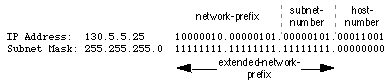
Figure 9: Subnet Mask
The standards describing modern routing protocols often refer to the extended-network-prefix- length rather than the subnet mask. The prefix length is equal to the number of contiguous one-bits in the traditional subnet mask. This means that specifying the network address 130.5.5.25 with a subnet mask of 255.255.255.0 can also be expressed as 130.5.5.25/24. The /<prefix-length> notation is more compact and easier to understand than writing out the mask in its traditional dotted-decimal format. This is illustrated in Figure 10.
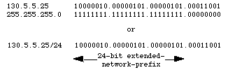
Figure 10: Extended-Network-Prefix Length
However, it is important to note that modern routing protocols still carry the subnet mask. There are no Internet standard routing protocols that have a one-byte field in their header that contains the number of bits in the extended-network prefix. Rather, each routing protocol is still required to carry the complete four-octet subnet mask.
Subnet Design Considerations
The deployment of an addressing
plan requires careful thought on the part of the network administrator.
There are four key questions that must be answered before any design
should be undertaken:
1) How many total subnets does the organization
need today?
2) How many total subnets will the organization need in the
future?
3) How many hosts are there on the organization's largest
subnet today?
4) How many hosts will there be on the organization's
largest subnet in the future?
The first step in the planning process is to take the maximum number of subnets required and round up to the nearest power of two. For example, if a organization needs 9 subnets, 23 (or 8) will not provide enough subnet addressing space, so the network administrator will need to round up to 24 (or 16). When performing this assessment, it is critical that the network administrator always allow adequate room for future growth. For example, if 14 subnets are required today, then 16 subnets might not be enough in two years when the 17th subnet needs to be deployed. In this case, it might be wise to allow for more growth and select 25 (or 32) as the maximum number of subnets.
The second step is to make sure that there are enough host addresses for the organization's largest subnet. If the largest subnet needs to support 50 host addresses today, 25 (or 32) will not provide enough host address space so the network administrator will need to round up to 26 (or 64).
The final step is to make sure that the organization's address allocation provides enough bits to deploy the required subnet addressing plan. For example, if the organization has a single /16, it could easily deploy 4-bits for the subnet-number and 6-bits for the host number. However, if the organization has several /24s and it needs to deploy 9 subnets, it may be required to subnet each of its /24s into four subnets (using 2 bits) and then build the internet by combining the subnets of 3 different /24 network numbers. An alternative solution, would be to deploy network numbers from the private address space (RFC 1918) for internal connectivity and use a Network Address Translator (NAT) to provide external Internet access.
Defining the Subnet Mask / Extended-Prefix Length
The first step
is to determine the number of bits required to define the six subnets.
Since a network address can only be subnetted along binary boundaries,
subnets must be created in blocks of powers of two [ 2 (21 ), 4
(22 ), 8 (23 ), 16 (24 ), etc. ]. Thus,
it is impossible to define an IP address block such that it contains
exactly six subnets. For this example, the network administrator must
define a block of 8 (23 ) and have two unused subnets that can
be reserved for future growth.
Since 8 = 23 , three bits are required to enumerate the eight subnets in the block. In this example, the organization is subnetting a /24 so it will need three more bits, or a /27, as the extended-network-prefix. A 27-bit extended-network-prefix can be expressed in dotted-decimal notation as 255.255.255.224. This is illustrated in Figure 11.
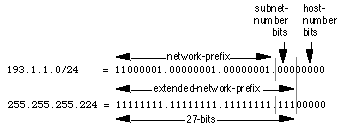
Figure 11: Example #1 - Defining the Subnet Mask/Extended-Prefix Length
A 27-bit extended-network-prefix leaves 5 bits to define host addresses on each subnet. This means that each subnetwork with a 27-bit prefix represents a contiguous block of 25 (32) individual IP addresses. However, since the all-0s and all-1s host addresses cannot be allocated, there are 30 (25 -2) assignable host addresses on each subnet.
Defining Each of the Subnet Numbers
The eight subnets will be
numbered 0 through 7. Throughout the remainder of this paper, the XXX2
notation indicates the binary representation of the number. The 3-bit
binary representation of the decimal values 0 through 7 are: 0 (0002 ), 1
(0012 ), 2 (0102 ), 3 (0112 ), 4 (1002 ), 5 (1012 ), 6 (1102 ), and 7
(1112 ).
In general, to define Subnet #n, the network administrator places the binary representation of n into the bits of the subnet-number field. For example, to define Subnet #6, the network administrator simply places the binary representation of 6 (1102 ) into the 3-bits of the subnet-number field.
The eight subnet numbers for this example are given below. The italicized portion of each address identifies the extended-network-prefix, while the bold digits identify the 3- bits representing the subnet-number field:
Base Net: 11000001.00000001.00000001 .00000000 =
193.1.1.0/24
Subnet #0:
11000001.00000001.00000001.000 00000 =
193.1.1.0/27
Subnet #1:
11000001.00000001.00000001.001 00000 =
193.1.1.32/27
Subnet #2:
11000001.00000001.00000001.010 00000 =
193.1.1.64/27
Subnet #3:
11000001.00000001.00000001.011 00000 =
193.1.1.96/27
Subnet #4:
11000001.00000001.00000001.100 00000 = 193.1.1.128/27
Subnet #5: 11000001.00000001.00000001.101 00000 =
193.1.1.160/27
Subnet #6:
11000001.00000001.00000001.110 00000 =
193.1.1.192/27
Subnet #7:
11000001.00000001.00000001.111 00000 = 193.1.1.224/27
An easy way to check if the subnets are correct is to ensure that they are all multiples of the Subnet #1 address. In this case, all subnets are multiples of 32: 0, 32, 64, 96, ...
The All-0s Subnet and The All-1s Subnet
When subnetting was
first defined in RFC 950, it prohibited the use of the all-0s and the
all-1s subnet. The reason for this restriction was to eliminate situations
that could potentially confuse a classful router. Note that today a router
can be both classless and classful at the same time - it could be running
RIP-1 (a classful protocol) and BGP-4 (a classless protocol) at the same
time.
With respect to the all-0s subnet, a router requires that each routing table update include the route/<prefix-length> pair to differentiate between a route to the all-0s subnet and a route to the entire network. For example, when using RIP-1 which does not supply a mask or prefix-length with each route, the routing advertisements for subnet 193.1.1.0/27 and for network 193.1.1.0/24 are identical - 193.1.1.0. Without somehow knowing the prefix-length or mask, a router cannot tell the difference between a route to the all-0s subnet and the route to the entire network! This is illustrated in Figure 12.
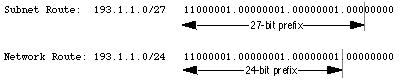
Figure 12: Differentiating Between a Route to the All-0s Subnet and the Entire Network
Regarding the all-1s subnet, a router requires that each routing table entry include the prefix-length so that it can determine if a broadcast (directed or all-subnets) should be sent only to the all-1s subnet or to the entire network. For example, when the routing table does not contain a mask or prefix-length for each route, confusion can occur because the same broadcast address (193.1.1.255) is used for both for the entire network 193.1.1.0/24 and the all-1s subnet 193.1.1.224/27. This is illustrated in Figure 13.
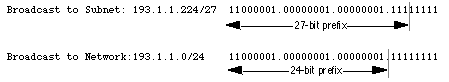
Figure 13: Identifying a Broadcast to the All-1s Subnet and the Entire Network
Note that by default, NETBuilder® software permits the forwarding of traffic to a directed broadcast address but does not forward traffic to the all-subnets broadcast address. The network administrator can modify this behavior via the -IP CONTrol parameter switches FwdSubnetBcast | NoFwdSubnetBcast and FwdAllSubnetBcast | NoFwdAllSubnetBcast.
With the development of routing protocols that supply the mask or
prefix-length with each route, the address space defined by the all-0s and
all-1s subnets is once again usable despite the cautions in RFC 950. As a
result, vendors have begun to accommodate user demand and permit the
configuration of the all-0s and all-1s subnets on router interfaces. There
are three factors that determine when these subnets can be used with
NETBuilder software.
To support the deployment of the all-0s and all-1s subnets, the IGP must either carry extended-network-prefixes or have a mechanism to map each route to its extended-network- prefix. Both OSPF and I-IS-IS carry extended-network-prefixes, so they support the deployment of the all-0s and all-1s subnets in arbitrarily complex topologies. RIP-1 does not carry extended-network-prefixes but the RcvSubnetMask parameter along with the -RIPIP CONTrol (..[Aggregate| NoAggregate], [DeAggregate| NoDeAggregate]) switches support the deployment of the all-0s and all-1s subnets in simple topologies.
NETBuilder software has taken a phased approach in its support for the deployment of the all-0s and all-1s subnets. Table 2 shows the NETBuilder software version number that first implemented the various features that support the deployment of these subnets.
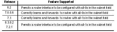
Table 2: NETBuilder Software Features Supporting the All-0s and All-1s Subnets
Finally, the other routers in the organization's network need to be able to correctly interpret, learn, and forward traffic to other subnetworks with all-0s and all-1s in their subnet number field.
Defining Host Addresses for Each Subnet
According to Internet
practices, the host-number field of an IP address cannot contain all
0-bits or all 1-bits. The all-0s host-number identifies the base network
(or subnetwork) number, while the all-1s host-number represents the
broadcast address for the network (or subnetwork).
In our current example, there are 5 bits in the host-number field of each subnet address. This means that each subnet represents a block of 30 host addresses (25 -2 = 30, note that the 2 is subtracted because the all-0s and the all-1s host addresses cannot be used). The hosts on each subnet are numbered 1 through 30.
In general, to define the address assigned to Host #n of a particular subnet, the network administrator places the binary representation of n into the subnet's host-number field. For example, to define the address assigned to Host #15 on Subnet #2, the network administrator simply places the binary representation of 15 (011112 ) into the 5-bits of Subnet #2's host-number field.
The valid host addresses for Subnet #2 in our example are given below. The italicized portion of each address identifies the extended-network-prefix, while the bold digits identify the 5-bit host-number field:
Subnet #2: 11000001.00000001.00000001.010 00000 =
193.1.1.64/27
Host #1:
11000001.00000001.00000001.010 00001 =
193.1.1.65/27
Host #2:
11000001.00000001.00000001.010 00010 =
193.1.1.66/27
Host #3:
11000001.00000001.00000001.010 00011 =
193.1.1.67/27
Host #4:
11000001.00000001.00000001.010 00100 =
193.1.1.68/27
Host #5:
11000001.00000001.00000001.010 00101 =
193.1.1.69/27
.
.
Host #15:
11000001.00000001.00000001.010 01111 =
193.1.1.79/27
Host #16:
11000001.00000001.00000001.010 10000 =
193.1.1.80/27
.
.
Host #27:
11000001.00000001.00000001.010 11011 =
193.1.1.91/27
Host #28:
11000001.00000001.00000001.010 11100 =
193.1.1.92/27
Host #29:
11000001.00000001.00000001.010 11101 =
193.1.1.93/27
Host #30:
11000001.00000001.00000001.010 11110 = 193.1.1.94/27
The valid host addresses for Subnet #6 are given below. The italicized portion of each address identifies the extended-network-prefix, while the bold digits identify the 5-bit host-number field:
Subnet #6: 11000001.00000001.00000001.110 00000 =
193.1.1.192/27
Host #1:
11000001.00000001.00000001.110 00001 =
193.1.1.193/27
Host #2:
11000001.00000001.00000001.110 00010 =
193.1.1.194/27
Host #3:
11000001.00000001.00000001.110 00011 =
193.1.1.195/27
Host #4:
11000001.00000001.00000001.110 00100 =
193.1.1.196/27
Host #5:
11000001.00000001.00000001.110 00101 =
193.1.1.197/27
.
.
Host #15:
11000001.00000001.00000001.110 01111 =
193.1.1.207/27
Host #16:
11000001.00000001.00000001.110 10000 =
193.1.1.208/27
.
.
Host #27:
11000001.00000001.00000001.110 11011 =
193.1.1.219/27
Host #28:
11000001.00000001.00000001.110 11100 =
193.1.1.220/27
Host #29:
11000001.00000001.00000001.110 11101 =
193.1.1.221/27
Host #30:
11000001.00000001.00000001.110 11110 =
193.1.1.222/27
Defining the Broadcast Address for Each Subnet 11000001.00000001.00000001.010
The broadcast
address for Subnet #2 is the all 1's host address or:
Note that the broadcast address for Subnet #2 is exactly one less than the base address for Subnet #3 (193.1.1.96). This is always the case - the broadcast address for Subnet #n is one less than the base address for Subnet #(n+1).
The broadcast address for Subnet #6 is simply the all 1's host address
or:
11000001.00000001.00000001.110
Again, the broadcast address for Subnet #6 is exactly one less than the base address for Subnet #7 (193.1.1.224).
Defining the Subnet Mask / Extended-Prefix Length
The first step
is to determine the number of bits required to define 60 hosts on each
subnet. Since a block of host address can only be assigned along binary
boundaries, host address blocks can only be created in powers of two. This
means that it is impossible to create a block that contains exactly 60
host addresses. To support 60 hosts, the network administrator must define
a minimum address block of 62 (26 -2) host addresses. However,
this choice would only provide two unused host addresses on each subnet
for future growth. Since this does not appear to be adequate to support
additional growth, the network administrator elects to define a block of
126 (27 -2) host addresses and has 66 addresses on each subnet
for future growth. A block of 126 host addresses requires 7-bits in the
host-number field.
The next step is to determine the subnet mask/extended-prefix length. Since 7-bits of the 32-bit IP address are required for the host-number field, the extended-prefix must be a /25 (25 = 32-7). A 25-bit extended-network-prefix can be expressed in dotted-decimal notation as 255.255.255.128. This is illustrated in Figure 14.
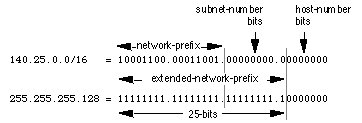
Figure 14: Example #2 - Defining the Subnet Mask/Extended-Prefix Length
Figure 14 shows that the 25-bit extended-prefix assigns 9-bits to the subnet number field. Since 29 = 512, nine bits allow the definition of 512 subnets. Depending on the organization's requirements, the network administrator could have elected to assign additional bits to the host-number field (allowing more hosts on each subnet) and reduce the number of bits in the subnet-number field (decreasing the total number of subnets that can be defined).
Although this example creates a rather large number of subnets, it provides an interesting example because it illustrates what happens to the dotted-decimal representation of a subnet address when the subnet-number bits extend across an octet boundary. It should be mentioned that the same type of confusion can also occur when the host-number bits extend across an octet boundary.
Defining Each of the Subnet Numbers
The 512 subnets will be
numbered 0 through 511. The 9-bit binary representation of the decimal
values 0 through 511 are: 0 (0000000002 ), 1 (0000000012 ), 2 (0000000102
), 3 (0000000112 ), ..., 511 (1111111112 ). To define subnet #3, the
network administrator places the binary representation of 3 (0000000112 )
into the 9-bits of the subnet-number field.
The 512 subnet numbers for
this example are given below. The italicized portion of each address
identifies the extended-network-prefix, while the bold digits
identify the 9- bits representing the subnet-number field:
Base Net: 10001100.00011001 .00000000.00000000 =
140.25.0.0/16
Subnet #0:
10001100.00011001.00000000. 0 0000000 =
140.25.0.0/25
Subnet #1:
10001100.00011001.00000000.1 0000000 =
140.25.0.128/25
Subnet #2:
10001100.00011001.00000001.0 0000000 =
140.25.1.0/25
Subnet #3:
10001100.00011001.00000001.1 0000000 =
140.25.1.128/25
Subnet #4:
10001100.00011001.00000010.0 0000000 =
140.25.2.0/25
Subnet #5:
10001100.00011001.00000010.1 0000000 =
140.25.2.128/25
Subnet #6:
10001100.00011001.00000011.0 0000000 =
140.25.3.0/25
Subnet #7:
10001100.00011001.00000011.1 0000000 =
140.25.3.128/25
Subnet #8:
10001100.00011001.00000100.0 0000000 =
140.25.4.0/25
Subnet #9:
10001100.00011001.00000100.1 0000000 =
140.25.4.128/25
.
.
Subnet #510:
10001100.00011001.11111111.0 0000000 =
140.25.255.0/25
Subnet #511:
10001100.00011001.11111111.1 0000000 =
140.25.255.128/25
Notice how sequential subnet numbers do not appear to be sequential when expressed in dotted-decimal notation. This can cause a great deal of misunderstanding and confusion since everyone believes that dotted-decimal notation makes it much easier for human users to understand IP addressing. In this example, the dotted-decimal notation obscures rather than clarifies the subnet numbering scheme!
Defining Hosts Addresses for Each Subnet
In this example there
are 7 bits in the host-number field of each subnet address. As discussed
earlier, this means that each subnet represents a block of 126 host
addresses. The hosts on each subnet will be numbered 1 through 126.
The valid host addresses for Subnet #3 are given below. The italicized portion of each address identifies the extended-network-prefix, while the bold digits identify the 7-bit host-number field:
Subnet #3: 10001100.00011001.00000001.1 0000000 =
140.25.1.128/25
Host #1:
10001100.00011001.00000001.1 0000001 =
140.25.1.129/25
Host #2:
10001100.00011001.00000001.1 0000010 =
140.25.1.130/25
Host #3:
10001100.00011001.00000001.1 0000011 =
140.25.1.131/25
Host #4:
10001100.00011001.00000001.1 0000100 =
140.25.1.132/25
Host #5:
10001100.00011001.00000001.1 0000101 =
140.25.1.133/25
Host #6:
10001100.00011001.00000001.1 0000110 =
140.25.1.134/25
.
.
Host #62:
10001100.00011001.00000001.1 0111110 =
140.25.1.190/25
Host #63:
10001100.00011001.00000001.1 0111111 =
140.25.1.191/25
Host #64:
10001100.00011001.00000001.1 1000000 =
140.25.1.192/25
Host #65:
10001100.00011001.00000001.1 1000001 =
140.25.1.193/25
.
.
Host #123:
10001100.00011001.00000001.1 1111011 =
140.25.1.251/25
Host #124:
10001100.00011001.00000001.1 1111100 =
140.25.1.252/25
Host #125:
10001100.00011001.00000001.1 1111101 =
140.25.1.253/25
Host #126:
10001100.00011001.00000001.1 1111110 =
140.25.1.254/25
Defining the Broadcast Address for Each Subnet 10001100.00011001.00000001.1
The broadcast
address for Subnet #3 is the all 1's host address or:
As is true in general, the broadcast address for Subnet #3 is exactly one less than the base address for Subnet #4 (140.25.2.0).
Additional Practice with Subnetworks
Please turn to Appendix C
for practice exercises to further your understanding of subnetting.
RIP-1 Permits Only a Single Subnet Mask
When using RIP-1, subnet
masks have to be uniform across the entire network-prefix. RIP-1 allows
only a single subnet mask to be used within each network number because it
does not provide subnet mask information as part of its routing table
update messages. In the absence of this information, RIP-1 is forced to
make very simple assumptions about the mask that should be applied to any
of its learned routes.
How does a RIP-1 based router know what mask to apply to a route when it learns a new route from a neighbor? If the router has a subnet of the same network number assigned to a local interface, it assumes that the learned subnetwork was defined using the same mask as the locally configured interface. However, if the router does not have a subnet of the learned network number assigned to a local interface, the router has to assume that the network is not subnetted and applies the route's natural classful mask.
Assuming that Port 1 of a router has been assigned the IP address
130.24.13.1/24 and that Port 2 has been assigned the IP address
200.14.13.2/24. If the router learns about network 130.24.36.0 from a
neighbor, it applies a /24 mask since Port 1 is configured with another
subnet of the 130.24.0.0 network. However, when the router learns about
network 131.25.0.0 from a neighbor, it assumes a "natural" /16 mask since
it has no other masking information available.
How does a RIP-1 based
router know if it should include the subnet-number bits in a routing table
update to a RIP-1 neighbor? A router executing RIP-1 will only advertise
the subnet-number bits on another port if the update port is configured
with a subnet of the same network number. If the update port is configured
with a different subnet or network number, the router will only advertise
the network portion of the subnet route and "zero-out" the subnet-number
field.
For example, assume that Port 1 of a router has been assigned the IP address 130.24.13.1/24 and that Port 2 has been assigned the IP address 200.14.13.2/24. Also, assume that the router has learned about network 130.24.36.0 from a neighbor. Since Port 1 is configured with another subnet of the 130.24.0.0 network, the router assumes that network 130.24.36.0 has a /24 subnet mask. When it comes to advertise this route, it advertises 130.24.36.0 on Port 1, but it only advertises 130.24.0.0 on Port 2.
For these reasons, RIP-1 is limited to only a single subnet mask for each network number. However, there are several advantages to be gained if more than one subnet mask can be assigned to a given IP network number:
Efficient Use of the Organization's Assigned IP Address
Space
VLSM supports more efficient use of an organization's
assigned IP address space. One of the major problems with the earlier
limitation of supporting only a single subnet mask across a given
network-prefix was that once the mask was selected, it locked the
organization into a fixed-number of fixed-sized subnets. For example,
assume that a network administrator decided to configure the 130.5.0.0/16
network with a /22 extended-network-prefix.
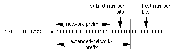
Figure 15: 130.5.0.0/16 with a /22 Extended-Network Prefix
Please refer to Figure 15. A /16 network with a /22 extended-network prefix permits 64 subnets (26 ), each of which supports a maximum of 1,022 hosts (2 10 -2). This is fine if the organization wants to deploy a number of large subnets, but what about the occasional small subnet containing only 20 or 30 hosts? Since a subnetted network could have only a single mask, the network administrator was still required to assign the 20 or 30 hosts to a subnet with a 22-bit prefix. This assignment would waste approximately 1,000 IP host addresses for each small subnet deployed! Limiting the association of a network number with a single mask did not encourage the flexible and efficient use of an organization's address space.
One solution to this problem was to allow a subnetted network to be assigned more than one subnet mask. Assume that in the previous example, the network administrator is also allowed to configure the 130.5.0.0/16 network with a /26 extended-network-prefix. Please refer to Figure 16. A /16 network address with a /26 extended-network prefix permits 1024 subnets (210 ), each of which supports a maximum of 62 hosts (26 -2). The /26 prefix would be ideal for small subnets with less than 60 hosts, while the /22 prefix is well suited for larger subnets containing up to 1000 hosts.
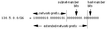
Figure 16: 130.5.0.0/16 with a /26 Extended-Network Prefix
11.0.0.0./8
11.1.0.0/16
11.2.0.0/16
11.3.0.0/16
11.252.0.0/16
11.253.0.0/16
11.254.0.0/16
11.1.1.0/24
11.1.2.0/24
11.1.253.0/24
11.1.254.0/24
11.253.32.0/19
11.253.64.0/19
11.253.160.0/19
11.253.192.0/19
11.1.253.32/27
11.1.253.64/27
11.1.253.160/27
11.1.253.192/27
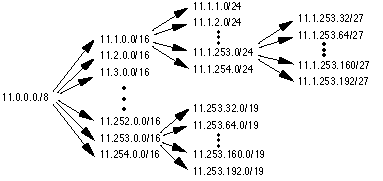
Figure 17: VLSM Permits the Recursive Division of a Network Prefix
In Figure 17, the 11.0.0.0/8 network is first configured with a /16 extended-network-prefix. The 11.1.0.0/16 subnet is then configured with a /24 extended-network-prefix and the 11.253.0.0/16 subnet is configured with a /19 extended-network-prefix. Note that the recursive process does not require that the same extended-network-prefix be assigned at each level of the recursion. Also, the recursive sub-division of the organization's address space can be carried out as far as the network administrator needs to take it.
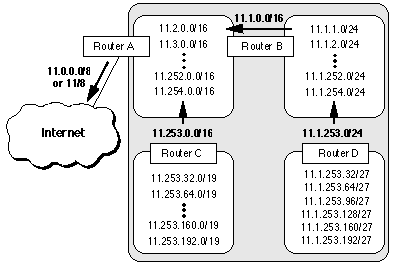
Figure 18: VLSM Permits Route Aggregation - Reducing Routing Table Size
Figure 18 illustrates how a planned and thoughtful allocation of VLSM can reduce the size of an organization's routing tables. Notice how Router D is able to summarize the six subnets behind it into a single advertisement (11.1.253.0/24) and how Router B is able to aggregate all of subnets behind it into a single advertisement. Likewise, Router C is able to summarize the six subnets behind it into a single advertisement (11.253.0.0/16). Finally, since the subnet structure is not visible outside of the organization, Router A injects a single route into the global Internet's routing table -11.0.0.0/ 8 (or 11/8).
1) How many total subnets does this level need today?
2) How many
total subnets will this level need in the future?
3) How many hosts are
there on this level's largest subnet today?
4) How many hosts will
there be on this level's largest subnet be in the future?
At each level, the design team must make sure that they have enough extra bits to support the required number of sub-entities in the next and further levels of recursion.
Assume that a network is spread out over a number of sites. For example, if an organization has three campuses today it probably needs 3-bits of subnetting (23 = 8) to allow the addition of more campuses in the future. Now, within each campus, there is likely to be a secondary level of subnetting to identify each building. Finally, within each building, a third level of subnetting might identify each of the individual workgroups. Following this hierarchical model, the top level is determined by the number of campuses, the mid-level is based on the number of buildings at each site, and the lowest level is determined by the "maximum number of subnets/maximum number of users per subnet" in each building.
The deployment of a hierarchical subnetting scheme requires careful planning. It is essential that the network designers recursively work their way down through their addressing plan until they get to the bottom level. At the bottom level, they must make sure that the leaf subnets are large enough to support the required number of hosts. When the addressing plan is deployed, the addresses from each site will be aggregable into a single address block that keeps the backbone routing tables from becoming too large.
Routing Protocols Must Carry Extended-Network-Prefix
Lengths
Modern routing protocols, such as OSPF and I-IS-IS, enable
the deployment of VLSM by providing the extended-network-prefix length or
mask value along with each route advertisement. This permits each
subnetwork to be advertised with its corresponding prefix length or mask.
If the routing protocols did not carry prefix information, a router would
have to either assume that the locally configured prefix length should be
applied, or perform a look-up in a statically configured prefix table that
contains all of the required masking information. The first alternative
cannot guarantee that the correct prefix is applied, and static tables do
not scale since they are difficult to maintain and subject to human error.
The bottom line is that if you want to deploy VLSM in a complex topology, you must select OSPF or I-IS-IS as the Interior Gateway Protocol (IGP) rather than RIP-1! It should be mentioned that RIP-2, defined in RFC 1388, improves the RIP protocol by allowing it to carry extended-network-prefix information. Therefore, RIP-2 supports the deployment of VLSM.
Forwarding Algorithm is Based on the "Longest Match"
All routers
must implement a consistent forwarding algorithm based on the "longest
match" algorithm. The deployment of VLSM means that the set of networks
associated with extended-network-prefixes may manifest a subset
relationship. A route with a longer extended-network-prefix describes a
smaller set of destinations than the same route with a shorter
extended-network-prefix. As a result, a route with a longer
extended-network-prefix is said to be "more specific" while a route with a
shorter extended-network-prefix is said to be "less specific." Routers
must use the route with the longest matching extended-network-prefix (most
specific matching route) when forwarding traffic.
For example, if a packet's destination IP address is 11.1.2.5 and there are three network prefixes in the routing table (11.1.2.0/24, 11.1.0.0/16, and 11.0.0.0/8), the router would select the route to 11.1.2.0/24. The 11.1.2.0/24 route is selected because its prefix has the greatest number of corresponding bits in the Destination IP address of the packet. This is illustrated in Figure 19.
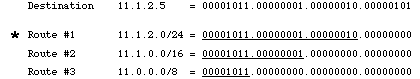
Figure 19: Best Match is with the Route Having the Longest Prefix (Most Specific)
There is a very subtle but extremely important issue here. Since the destination address matches all three routes, it must be assigned to a host which is attached to the 11.1.2.0/24 subnet. If the 11.1.2.5 address is assigned to a host that is attached to the 11.1.0.0/16 or 11.0.0.0/8 subnet, the routing system will never route traffic to the host since the "longest match algorithm" assumes that the host is part of the 11.1.2.0/24 subnet. This means that great care must be taken when assigning host addresses to make sure that every host is reachable!
Topologically Significant Address Assignment
Since OSPF and
I-IS-IS convey the extended-network-prefix information with each route,
the VLSM subnets can be scattered throughout an organization's topology.
However, to support hierarchical routing and reduce the size of an
organization's routing tables, addresses should be assigned so that they
are topologically significant.
Hierarchical routing requires that addresses be assigned to reflect the actual network topology. This reduces the amount of routing information by taking the set of addresses assigned to a particular region of the topology, and aggregating them into a single routing advertisement for the entire set. Hierarchical routing allows this to be done recursively at various points within the hierarchy of the routing topology. If addresses do not have a topological significance, aggregation cannot be performed and the size of the routing tables cannot be reduced. Remember this point when we discuss CIDR aggregation later in this paper.
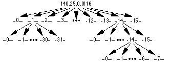
Figure 20: Address Strategy for VLSM Example
The first step of the subnetting process divides the base network address into 16 equal-sized address blocks. Then Subnet #1 is divided it into 32 equal-sized address blocks and Subnet #14 is divided into 16 equal-sized address blocks. Finally, Subnet #14-14 is divided into 8 equal-sized address blocks.
Define the 16 Subnets of 140.25.0.0/16
The first step in the
subnetting process divides the base network address into 16 equal-size
address blocks. This is illustrated in Figure 21.
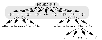
Figure 21: Define the 16 Subnets for 140.25.0.0/16
Since 16 = 24 , four bits are required to uniquely identify each of the 16 subnets. This means that the organization needs four more bits, or a /20, in the extended-network-prefix to define the 16 subnets of 140.25.0.0/16. Each of these subnets represents a contiguous block of 212 (or 4,096) network addresses.
The 16 subnets of the 140.25.0.0/16 address block are given below. The subnets are numbered 0 through 15. The italicized portion of each address identifies the extended-network- prefix, while the bold digits identify the 4-bits representing the subnet-number field:
Base Network: 10001100.00011001 .00000000.00000000 =
140.25.0.0/16
Subnet #0:
10001100.00011001.0000 0000.00000000 =
140.25.0.0/20
Subnet #1:
10001100.00011001.0001 0000.00000000 =
140.25.16.0/20
Subnet #2:
10001100.00011001.0010 0000.00000000 =
140.25.32.0/20
Subnet #3:
10001100.00011001.0011 0000.00000000 =
140.25.48.0/20
Subnet #4:
10001100.00011001.0100 0000.00000000 =
140.25.64.0/20
:
:
Subnet #13:
10001100.00011001.1101 0000.00000000 =
140.25.208.0/20
Subnet #14:
10001100.00011001.1110 0000.00000000 =
140.25.224.0/20
Subnet #15:
10001100.00011001.1111 0000.00000000 =
140.25.240.0/20
Define the Host Addresses for Subnet #3 (140.25.48.0/20)
Let's
examine the host addresses that can be assigned to Subnet #3
(140.25.48.0/20). This is illustrated in Figure 22.
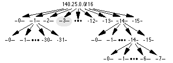
Figure 22: Define the Host Addresses for Subnet #3 (140.25.48.0/20)
Since the host-number field of Subnet #3 contains 12 bits, there are
4,094 valid host addresses (212 -2) in the address block. The
hosts are numbered 1 through 4,094.
The valid host addresses for Subnet
#3 are given below. The italicized portion of each address identifies the
extended-network-prefix, while the bold digits identify the 12-bit
host-number field:
Subnet #3: 10001100.00011001.0011 0000.00000000 =
140.25.48.0/20
Host #1:
10001100.00011001.0011 0000.00000001 =
140.25.48.1/20
Host #2:
10001100.00011001.0011 0000.00000010 =
140.25.48.2/20
Host #3:
10001100.00011001.0011 0000.00000011 =
140.25.48.3/20
:
:
Host #4093:
10001100.00011001.0011 1111.11111101 =
140.25.63.253/20
Host #4094:
10001100.00011001.0011 1111.11111110 =
140.25.63.254/20
The broadcast address for Subnet #3 is the all 1's host address or:
10001100.00011001.0011
The broadcast address for Subnet #3 is exactly one less than the base address for Subnet #4 (140.25.64.0).
Define the Sub-Subnets for Subnet #14 (140.25.224.0/20)
After
the base network address is divided into sixteen subnets, Subnet #14 is
further subdivided into 16 equal-size address blocks. This is illustrated
in Figure 23.
Figure 23: Define the Sub-Subnets for Subnet #14 (140.25.224.0/20)
Since 16 = 24 , four more bits are required to identify each
of the 16 subnets. This means that the organization will need to use a /24
as the extended-network-prefix length.
The 16 subnets of the
140.25.224.0/20 address block are given below. The subnets are numbered 0
through 15. The italicized portion of each sub-subnet address identifies
the extended-network-prefix, while the bold digits identify the
4-bits representing the sub-subnet-number field:
Subnet #14: 10001100.00011001.1110 0000.00000000 =
140.25.224.0/20
Subnet #14-0:
10001100.00011001.1110 0000 .00000000 =
140.25.224.0/24
Subnet #14-1:
10001100.00011001.1110 0001 .00000000 =
140.25.225.0/24
Subnet #14-2:
10001100.00011001.1110 0010 .00000000 =
140.25.226.0/24
Subnet #14-3:
10001100.00011001.1110 0011 .00000000 =
140.25.227.0/24
Subnet #14-4:
10001100.00011001.1110 0100 .00000000 =
140.25.228.0/24
:
:
Subnet #14-14:
10001100.00011001.1110 1110 .00000000 =
140.25.238.0/24
Subnet #14-15:
10001100.00011001.1110 1111 .00000000 =
140.25.239.0/24
Define Host Addresses for Subnet #14-3 (140.25.227.0/24)
Let's
examine the host addresses that can be assigned to Subnet #14-3
(140.25.227.0/24). This is illustrated in Figure 24.

Figure 24: Define the Host Addresses for Subnet #14-3 (140.25.227.0/24)
Each of the subnets of Subnet #14-3 has 8 bits in the host-number field. This means that each subnet represents a block of 254 valid host addresses (28 -2). The hosts are numbered 1 through 254.
The valid host addresses for Subnet #14-3 are given below. The italicized portion of each address identifies the extended-network-prefix, while the bold digits identify the 8- bit host-number field:
Subnet #14-3: 10001100.00011001.11100011 .00000000 =
140.25.227.0/24
Host #1
10001100.00011001.11100011 .00000001 =
140.25.227.1/24
Host #2
10001100.00011001.11100011 .00000010 =
140.25.227.2/24
Host #3
10001100.00011001.11100011 .00000011 =
140.25.227.3/24
Host #4
10001100.00011001.11100011 .00000100 =
140.25.227.4/24
Host #5
10001100.00011001.11100011 .00000101 =
140.25.227.5/24
.
.
Host #253
10001100.00011001.11100011 .11111101 =
140.25.227.253/24
Host #254
10001100.00011001.11100011 .11111110 =
140.25.227.254/24
The broadcast address for Subnet #14-3 is the all 1's host address
or:
10001100.00011001.11100011.
The broadcast address for Subnet #14-3 is exactly one less than the base address for Subnet #14-4 (140.25.228.0).
Define the Sub 2 -Subnets for Subnet #14-14
(140.25.238.0/24)
After Subnet #14 was divided into sixteen
subnets, Subnet #14-14 is further subdivided into 8 equal-size address
blocks. This is illustrated in Figure 25.
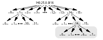
Figure 25: Define the Sub 2 -Subnets for Subnet #14-14 (140.25.238.0/24)
Since 8 = 23 , three more bits are required to identify each of the 8 subnets. This means that the organization will need to use a /27 as the extended-network-prefix length.
The 8 subnets of the 140.25.238.0/24 address block are given below. The subnets are numbered 0 through 7. The italicized portion of each sub-subnet address identifies the extended-network-prefix, while the bold digits identify the 3-bits representing the subnet 2 -number field:
Subnet #14-14: 10001100.00011001.11101110 .00000000 =
140.25.238.0/24
Subnet#14-14-0:
10001100.00011001.11101110.000 00000 =
140.25.238.0/27 Subnet#14-14-1:
10001100.00011001.11101110.001 00000 =
140.25.238.32/27 Subnet#14-14-2:
10001100.00011001.11101110.010 00000 =
140.25.238.64/27 Subnet#14-14-3:
10001100.00011001.11101110.011 00000 =
140.25.238.96/27 Subnet#14-14-4:
10001100.00011001.11101110.100 00000 =
140.25.238.128/27 Subnet#14-14-5:
10001100.00011001.11101110.101 00000 =
140.25.238.160/27 Subnet#14-14-6:
10001100.00011001.11101110.110 00000 =
140.25.238.192/27 Subnet#14-14-7:
10001100.00011001.11101110.111 00000 =
140.25.238.224/27
Define Host Addresses for Subnet #14-14-2
(140.25.238.64/27)
Let's examine the host addresses that can be
assigned to Subnet #14-14-2 (140.25.238.64/27). This is illustrated in
Figure 26.
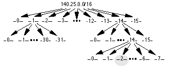
Figure 26: Define the Host Addresses for Subnet #14-14-2 (140.25.238.64/27)
Each of the subnets of Subnet #14-14 has 5 bits in the host-number field. This means that each subnet represents a block of 30 valid host addresses (25 -2). The hosts will be numbered 1 through 30.
The valid host addresses for Subnet #14-14-2 are given below. The italicized portion of each address identifies the extended-network-prefix, while the bold digits identify the 5-bit host-number field:
Subnet#14-14-2: 10001100.00011001.11101110.010 00000 =
140.25.238.64/27
Host #1
10001100.00011001.11101110.010 00001 =
140.25.238.65/27
Host #2
10001100.00011001.11101110.010 00010 =
140.25.238.66/27
Host #3
10001100.00011001.11101110.010 00011 =
140.25.238.67/27
Host #4
10001100.00011001.11101110.010 00100 =
140.25.238.68/27
Host #5
10001100.00011001.11101110.010 00101 =
140.25.238.69/27
.
.
Host #29
10001100.00011001.11101110.010 11101 =
140.25.238.93/27
Host #30
10001100.00011001.11101110.010 11110 =
140.25.238.94/27
The broadcast address for Subnet #14-14-2 is the all 1's host address
or:
10001100.00011001.11011100.010
The broadcast address for Subnet #6-14-2 is exactly one less than the base address for Subnet #14-14-3 (140.25.238.96).
Additional Practice with VLSM
Please turn to Appendix D for
practice exerciss to reinforce your understanding of VLSM.
Projected Internet growth figures made it clear that the first two problems were likely to become critical by 1994 or 1995. The response to these immediate challenges was the development of the concept of Supernetting or Classless Inter-Domain Routing (CIDR). The third problem, which is of a more long-term nature, is currently being explored by the IP Next Generation (IPng or IPv6) working group of the IETF.
CIDR was officially documented in September 1993 in RFC 1517, 1518,
1519, and 1520. CIDR supports two important features that benefit the
global Internet routing system:
Without the rapid deployment of CIDR in 1994 and 1995, the Internet routing tables would have in excess of 70,000 routes (instead of the current 30,000+) and the Internet would probably not be functioning today!
CIDR Promotes the Efficient Allocation of the IPv4 Address
Space
CIDR eliminates the traditional concept of Class A, Class B,
and Class C network addresses and replaces them with the generalized
concept of a "network-prefix." Routers use the network-prefix, rather than
the first 3 bits of the IP address, to determine the dividing point
between the network number and the host number. As a result, CIDR supports
the deployment of arbitrarily sized networks rather than the
standard 8-bit, 16- bit, or 24-bit network numbers associated with
classful addressing.
In the CIDR model, each piece of routing information is advertised with a bit mask (or prefix-length). The prefix-length is a way of specifying the number of leftmost contiguous bits in the network-portion of each routing table entry. For example, a network with 20 bits of network-number and 12-bits of host-number would be advertised with a 20-bit prefix length (a /20). The clever thing is that the IP address advertised with the /20 prefix could be a former Class A, Class B, or Class C. Routers that support CIDR do not make assumptions based on the first 3-bits of the address, they rely on the prefix-length information provided with the route.
In a classless environment, prefixes are viewed as bitwise contiguous blocks of the IP address space. For example, all prefixes with a /20 prefix represent the same amount of address space (212 or 4,096 host addresses). Furthermore, a /20 prefix can be assigned to a traditional Class A, Class B, or Class C network number. Figure 27 shows how each of the following /20 blocks represent 4,096 host addresses - 10.23.64.0/20, 130.5.0.0/20, and 200.7.128.0/20.
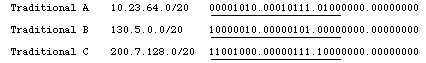
Figure 27: /20 Bitwise Contiguous Address Blocks
Table 3 provides information about the most commonly deployed CIDR address blocks. Referring to the Table, you can see that a /15 allocation can also be specified using the traditional dotted-decimal mask notation of 255.254.0.0. Also, a /15 allocation contains a bitwise contiguous block of 128K (131,072) IP addresses which can be classfully interpreted as 2 Class B networks or 512 Class C networks.
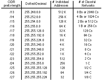
Table 3: CIDR Address Blocks
Host Implications for CIDR Deployment
It is important to note
that there may be severe host implications when you deploy CIDR based
networks. Since many hosts are classful, their user interface will not
permit them to be configured with a mask that is shorter than the
"natural" mask for a traditional classful address. For example, potential
problems could exist if you wanted to deploy 200.25.16.0 as a /20 to
define a network capable of supporting 4,094 (2 12 -2) hosts. The software
executing on each end station might not allow a traditional Class C
(200.25.16.0) to be configured with a 20-bit mask since the natural mask
for a Class C network is a 24-bit mask. If the host software supports
CIDR, it will permit shorter masks to be configured.
However, there will be no host problems if you were to deploy the 200.25.16.0/20 (a traditional Class C) allocation as a block of 16 /24s since non-CIDR hosts will interpret their local /24 as a Class C. Likewise, 130.14.0.0/16 (a traditional Class B) could be deployed as a block of 255 /24s since the hosts will interpret the /24s as subnets of a /16. If host software supports the configuration of shorter than expected masks, the network manager has tremendous flexibility in network design and address allocation.
Efficient Address Allocation
How does all of this lead to the
efficient allocation of the IPv4 address space? In a classful environment,
an Internet Service Provider (ISP) can only allocate /8, /16, or /24
addresses. In a CIDR environment, the ISP can carve out a block of its
registered address space that specifically meets the needs of each client,
provides additional room for growth, and does not waste a scarce resource.
Assume that an ISP has been assigned the address block 206.0.64.0/18. This block represents 16,384 (214) IP addresses which can be interpreted as 64 /24s. If a client requires 800 host addresses, rather than assigning a Class B (and wasting ~64,700 addresses) or four individual Class Cs (and introducing 4 new routes into the global Internet routing tables), the ISP could assign the client the address block 206.0.68.0/22, a block of 1,024 (210) IP addresses (4 contiguous /24s). The efficiency of this allocation is illustrated in Figure 28.
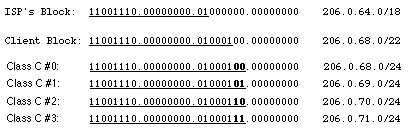
Figure 28: CIDR Supports Efficient Address Allocation
CIDR Address Allocation Example
For this example, assume that an
ISP owns the address block 200.25.0.0/16. This block represents 65, 536
(216) IP addresses (or 256 /24s).
From the 200.25.0.0/16 block it wants to allocate the 200.25.16.0/20 address block . This smaller block represents 4,096 (212) IP addresses (or 16 /24s).
Address Block 11001000.00011001.00010000.00000000 200.25.16.0/20
In
a classful environment, the ISP is forced to use the /20 as 16 individual
/24s.
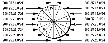
Figure 29: Slicing the Pie - Classful Environment
However, in a classless environment, the ISP is free to cut up the pie any way it wants. It could slice up the original pie into 2 pieces (each 1/2 of the address space) and assign one portion to Organization A, then cut the other half into 2 pieces (each 1/4 of the address space) and assign one piece to Organization B, and finally slice the remaining fourth into 2 pieces (each 1/8 of the address space) and assign it to Organization C and Organization D. Each of the individual organizations is free to allocate the address space within its "Intranetwork" as it sees fit. This is illustrated in Figure 30.
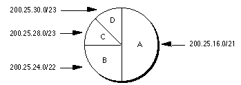
Figure 30: Slicing the Pie - Classless Environment
Step #1: Divide the address block 200.25.16.0/20 into two equal size slices. Each block represents one-half of the address space or 2,048 (211) IP addresses.
ISP's Block 11001000.00011001.00010000.00000000 200.25.16.0/20
Org
A: 11001000.00011001.00010000.00000000 200.25.16.0/21
Reserved:
11001000.00011001.00011000.00000000 200.25.24.0/21
Step #2: Divide the reserved block (200.25.24.0/21) into two equal size slices. Each block represents one-fourth of the address space or 1,024 (210) IP addresses.
Reserved 11001000.00011001.00011000.00000000 200.25.24.0/21
Org B:
11001000.00011001.00011000.00000000 200.25.24.0/22
Reserved
11001000.00011001.00011100.00000000 200.25.28.0/22
Step #3: Divide the reserved address block (200.25.28.0/22) into two equal size blocks. Each block represents one-eight of the address space or 512 (29) IP addresses.
Reserved 11001000.00011001.00011100.00000000 200.25.28.0/22
Org C:
11001000.00011001.00011100.00000000 200.25.28.0/23
Org D:
11001000.00011001.00011110.00000000 200.25.30.0/23
CIDR is Similar to VLSM
If CIDR appears to have the familiar
look and feel of VLSM, you're correct! CIDR and VLSM are essentially the
same thing since they both allow a portion of the IP address space to be
recursively divided into subsequently smaller pieces. The difference is
that with VLSM, the recursion is performed on the address space previously
assigned to an organization and is invisible to the global Internet. CIDR,
on the other hand, permits the recursive allocation of an address block by
an Internet Registry to a high-level ISP, to a mid-level ISP, to a
low-level ISP, and finally to a private organization's network.
Just like VLSM, the successful deployment of CIDR has three
prerequisites:
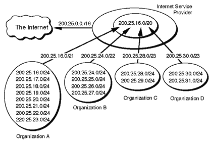
Figure 31: CIDR Reduces the Size of Internet Routing Tables
Figure 31 illustrates how the allocation described in previous CIDR example helps reduce the size of the Internet routing tables. Assume that a portion of the ISPs address block (200.25.16.0/20) has been allocated as described in the previous example. Organization A aggregates 8 /24s into a single advertisement (200.25.16.0/21), Organization B aggregates 4 /24s into a single advertisement (200.25.24.0/22), Organization C aggregates 2 /24s into a single advertisement (200.25.28.0/23), and Organization D aggregates 2 /24s into a single advertisement (200.25.30.0/23). Finally, the ISP is able to inject the 256 /24s in its allocation into the Internet with a single advertisement - 200.25.0.0/16!
It should be mentioned that route aggregation via BGP-4 is not automatic. The network engineers must configure each router to perform the required aggregation. The successful deployment of CIDR will allow the number of individual networks on the Internet to expand, while minimizing the number of routes in the Internet routing tables.
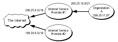
Figure 32: Routing Advertisements for Organization A
Since all of Organization A's routes are part of ISP #1's address
block, the routes to Organization A are implicitly aggregated via ISP #1's
aggregated announcement to the Internet. In other words, the eight
networks assigned to Organization A are hidden behind a single routing
advertisement. Using the longest match forwarding algorithm, Internet
routers will route traffic to host 200.25.17.25 to ISP #1, which will in
turn route the traffic to Organization A.
Now, for whatever reasons,
assume that Organization A decides to change its network provider to ISP
#2. This is illustrated in Figure 33.
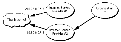
Figure 33: Organization A Changes Network Providers to ISP #2
The "best" thing for the size of the Internet's routing tables would be to have Organization A obtain a block of ISP #2's address space and renumber. This would allow the eight networks assigned to Organization A to be hidden behind the aggregate routing advertisement of ISP #2. Unfortunately, renumbering is a labor-intensive task which could be very difficult, if not impossible, for Organization A.
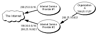
Figure 34: ISP #2 Injects a More-Specific Route into the Internet
The "best" thing for Organization A is to retain ownership of its address space and have ISP #2 advertise an "exception" (more specific) route into the Internet. The exception route allows all traffic for 200.25.0.0/16 to be sent to ISP #1, with the exception of the traffic to 200.25.16.0/21. This is accomplished by having ISP #2 advertise, in addition to its own 199.30.0.0/16 block, a route for 200.25.16.0/21. Please refer to Figure 34. Using the "longest match" forwarding algorithm, Internet routers will route traffic addressed to host 200.25.17.25 to ISP #2 which will in turn route the traffic to Organization A. Clearly, the introduction of a large number of exception routes can reduce the effectiveness of the CIDR deployment and eventually cause Internet routing tables to begin exploding again!
Additional Practice with CIDR
Please turn to Appendix E for several practice exercises to reinforce your understanding of CIDR.
Appeal to Return Unused IP Network Prefixes
RFC 1917 requests
that the Internet community return unused address blocks to the Internet
Assigned Numbers Authority (IANA) for redistribution. This includes unused
network numbers, addresses for networks that will never be connected to
the global Internet for security reasons, and sites that are using a small
percentage of their address space. RFC 1917 also petitions ISPs to return
unused network-prefixes that are outside of their assigned address blocks.
It will be interesting to see how the Internet community responds since
many organizations with unused addresses don't want to return them because
they are viewed as an asset.
Address Allocation for Private Internets
RFC 1918 requests that
organizations make use of the private Internet address space for hosts
that require IP connectivity within their enterprise network, but do not
require external connections to the global Internet. For this purpose, the
IANA has reserved the following three address blocks for private
internets:
10.0.0.0 - 10.255.255.255 (10/8 prefix) 172.16.0.0 - 172.31.255.255 (172.16/12 prefix) 192.168.0.0 - 192.168.255.255 (192.168/16 prefix)
Any organization that elects to use addresses from these reserved blocks can do so without contacting the IANA or an Internet registry. Since these addresses are never injected into the global Internet routing system, the address space can simultaneously be used by many different organizations.
The disadvantage to this addressing scheme is that it requires an organization to use a Network Address Translator (NAT) for global Internet access. However, the use of the private address space and a NAT make it much easier for clients to change their ISP without the need to renumber or "punch holes" in a previously aggregated advertisement. The benefits of this addressing scheme to the Internet is that it reduces the demand for IP addresses so large organizations may require only a small block of the globally unique IPv4 address space.
Address Allocation from the Reserved Class A Address Space
An
Internet draft, "Observations on the use of Components of the Class A
Address Space within the Internet" <draft-ietf-cidrd-classa-01.txt>,
explores the allocation of the upper-half of the currently reserved Class
A address space through delegated registries. As the demand for IP
addresses continues to grow, it appears that it may be necessary to
eventually allocate the 64.0.0.0/2 address space. Note that the 64.0.0.0/2
address block is huge and represents 25% of the IPv4 unicast address
space.
Implications of Address Allocation Policies
An Internet draft ,
"Implications of Various Address Allocation Policies for Internet Routing"
<draft-ietf-cidrd-addr-ownership-07.txt>, discusses the fundamental
issues that must be considered as the Internet develops a new unicast
address allocation and management policies. The draft compares the
benefits and limitations of an "address ownership" policy with an "address
lending" policy.
"Address ownership" means that when an address block is assigned to an organization, it remains allocated to that organization for as long as the organization wants to keep it. This means that the address block is "portable" and that the organization would be able to use it to gain access to the Internet no matter where the organization connects to the Internet. On the other hand, "address lending" means that an organization obtains its address block on a "loan" basis. If the loan ends, the organization can no longer use the borrowed address block, must obtain new addresses, and renumber before using them.
As we have seen, hierarchical routing requires that addresses reflect
the network topology in order to permit route aggregation. The draft
argues that there are two fundamental problems that break the hierarchical
addressing and routing model supported by CIDR:
The draft concludes with the recommendation that large providers, which can express their destinations with a single prefix, be assigned address blocks following the "address ownership" model. However, all allocations from these providers to a downstream clients should follow the "address lending" model. This means that if an organization changes its provider, the loan is canceled and the client will be required to renumber.
This draft has generated a tremendous amount of discussion within the Internet community about the concept of address ownership and what it means in the context of global routing. The authors present a strong argument that the Internet has to make a choice between either address ownership for all or a routable Internet - it can't have both! Smaller organizations that want to own their addresses have concerns about the difficulty of renumbering and their lack of self-determination if their provider or their provider's upstream provider changes its provider. Finally, ISPs have concerns because the term "large provider" has not been defined. At this time, the discussion continues since any criteria recommended by the IETF is bound to be perceived as unfair by some!
Procedures for Internet/Enterprise Renumbering (PIER)
In the
face of the "address ownership" vs. "address lending" debate, it is clear
that renumbering may become a critical issue in the late 1990s. Procedures
for Internet/Enterprise Renumbering (PIER) is a working group of the IETF
charged with the task of developing a renumbering strategy.
RFC 1916 is a request by PIER for the Internet community to provide assistance in the development of a series of documents describing how an organization might proceed to renumber its network. The ultimate goal of these documents is to provide education and practical experience to the Internet community.
Market-Based Allocation of IP Address Blocks
An Internet draft
,"Suggestions for Market-Based Allocation of IP Address Blocks"
<draft-ietf-cidrd-blocks-00.txt>, is a proposal to make IPv4 address
assignments transferable and condones the exchange of money as part of the
transfer procedure. It suggests that the Internet community embrace the
profit motive as an incentive to motivate organizations to act in ways
that will improve resource use. This proposal goes hand-in-hand with
another proposal to introduce financial incentives for route aggregation
(i.e., have ISPs levy a charge for each route advertised). The idea is to
move the decisions regarding scarce resources from a political atmosphere
to a financial environment which is better suited to deal with scarcity.
Minutes of the most recent IETF Proceedings are available from: http://www.ietf.cnri.reston.va.us/proceedings/directory.html
Information about the size and content of the Internet routing table is available on the Merit Web pages: http://www.ra.net/~ra/statistics/routes.html
CIDR Deployment (CIDRD)
For general information about the CIDRD
working group of the IETF and its charter: http://www.ietf.cnri.reston.va.us/html.charters/cidrd-charter.html
To subscribe to the CIDRD mailing list: cidrd-request@iepg.org
Internet Drafts published by the CIDRD working group are available from: http://www.ietf.cnri.reston.va.us/ids.by.wg/cidrd.html
Procedures for Internet/Enterprise Renumbering (PIER)
General
information about the PIER working group of the IETF and its charter is
available from: http://www.ietf.cnri.reston.va.us/html.charters/pier-charter.html
To subscribe to the PIER mailing list: pier-request@isi.edu
Papers developed by PIER are available from: http://www.isi.edu/div7/pier/
Dynamic Host Configuration (DHCP)
For information about the DHCP
working group, current Internet-Drafts, and Requests for Comments: http://www.ietf.cnri.reston.va.us/html.charters/dhc-charter.html
To access the DHCP Home Page: http://charlotte.acns.nwu.edu/internet/tech/dhcp/
To subscribe to the DHCP mailing list: host-conf-request@sol.eg.bucknell.edu
The DHCP mail list archive: ftp://ftp.bucknell.edu/pub/dhcp
IPng (IPNGWG)
For information about the IPng working group,
current Internet-Drafts, and Requests for Comments: http://www.ietf.cnri.reston.va.us/html.charters/ipngwg-charter.html
To access the IPng Home Page: http://playground.sun.com/pub/ipng/html/ipng-main.html
To subscribe to the IPng mailing list: majordomo@sunroof.eng.sun.com
The IPng mail list archive: ftp://parcftp.xerox.com/pub/ipng
Internet Drafts
Internet Drafts are available on the WWW
from: http://www.ietf.cnri.reston.va.us/1id-abstracts.html
"Suggestions
for Market-Based Allocation of IP Address Blocks",
<draft-ietf-cidrd-blocks- 00.txt>, P. Resnick, 02/23/1996. (24590
bytes)
"Observations on the use of Components of the Class A Address Space within the Internet", <draft-ietf-cidrd-classa-01.txt>, G.Huston, 12/22/1995. (21347 bytes)
Classless in-addr.arpa delegation", <draft-ietf-cidrd-classless-inaddr-00.txt>, H. Eidnes, G. de Groot, 01/18/1996. (13224 bytes)
"Implications of Various Address Allocation Policies for Internet Routing", <draft-ietf-cidrd- addr-ownership-07.txt>, Y. Rekhter, T. Li, 01/15/1996. (34866 bytes)
"Suggestions for Market-Based Allocation of IP Address Blocks", <draft-ietf-cidrd-blocks- 00.txt>, P. Resnick, 02/23/1996. (24590 bytes)
Textbooks
Comer, Douglas E. Internetworking with TCP/IP
Volume 1 Principles, Protocols, and Architecture Second Edition,
Prentice Hall, Inc. Englewood Cliffs, New Jersey, 1991
Huitema,
Christian. Routing in the Internet, Prentice Hall, Inc. Englewood
Cliffs, New Jersey, 1995
Stevens, W. Richard. TCP/IP Illustrated:
Volume 1 The Protocols, Addison Wesley Publishing Company, Reading MA,
1994
Wright, Gary and W. Richard Stevens. TCP/IP Illustrated: Volume
2 The Implementation, Addison Wesley Publishing Company, Reading MA,
1995
2. Complete the following table which provides practice in converting a number from decimal notation to binary format.
3. Express 145.32.59.24 in binary format and identify the address class:
4. Express 200.42.129.16 in binary format and identify the address class:
5. Express 14.82.19.54 in binary format and identify the address class:
Solutions to Classful IP Addressing Practice Exercises
1.
Complete the following table which provides practice in converting a
number from binary notation to decimal format.
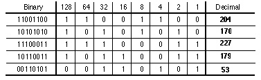
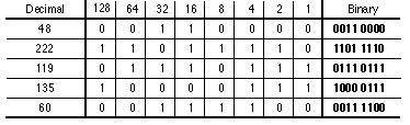
2. Complete the following table which provides practice in converting a number from decimal notation to binary format.
3. Express 145.32.59.24 in binary format and identify the classful
prefix length.
10010001.00100000.00111011.00011000 /16 or Class B
4. Express 200.42.129.16 in binary format and identify the classful
prefix length.
11001000.00101010.10000001.00010000 /24 or Class C
5. Express 14.82.19.54 in binary format and identify the classful
prefix length.
00001110.01010010. 00010011.00110110 /8 or Class A
1. __________ binary digits are required to define eight subnets.
2. Specify the extended-network-prefix that allows the creation of 8
subnets.
__________________________________________________________________
3. Express the subnets in binary format and dotted decimal
notation:
#0
________________________________________________________________
#1
________________________________________________________________
#2
________________________________________________________________
#3
________________________________________________________________
#4
________________________________________________________________
#5
________________________________________________________________
#6
________________________________________________________________
#7
________________________________________________________________
4. List the range of host addresses that can be assigned to Subnet #3
(132.45.96.0/19).
__________________________________________________________________
__________________________________________________________________
__________________________________________________________________
__________________________________________________________________
__________________________________________________________________
5. What is the broadcast address for Subnet #3
(132.45.96.0/19).
__________________________________________________________________
Subnetting Exercise #2
1. Assume that you have been assigned the 200.35.1.0/24 network block.
Define an extended-network-prefix that allows the creation of 20 hosts on
each
subnet.
__________________________________________________________________
2. What is the maximum number of hosts that can be assigned to each
subnet?
__________________________________________________________________
3. What is the maximum number of subnets that can be
defined?
__________________________________________________________________
4. Specify the subnets of 200.35.1.0/24 in binary format and dotted
decimal
notation.
__________________________________________________________________
__________________________________________________________________
__________________________________________________________________
__________________________________________________________________
__________________________________________________________________
__________________________________________________________________
__________________________________________________________________
__________________________________________________________________
5. List range of host addresses that can be assigned to Subnet #6
(200.35.1.192/27)
__________________________________________________________________
__________________________________________________________________
__________________________________________________________________
__________________________________________________________________
__________________________________________________________________
__________________________________________________________________
__________________________________________________________________
__________________________________________________________________
__________________________________________________________________
6. What is the broadcast address for subnet
200.35.1.192/27?
__________________________________________________________________
Solution for Subnetting Exercise #1
Assume that you have been
assigned the 132.45.0.0/16 network block. You need to establish 8 subnets.
1. Three binary digits are required to define the eight subnets.
2. Specify the extended-network-prefix that allows the creation of 8
subnets.
/19 or 255.255.224.0
3. Express the subnets in binary format and dotted decimal
notation:
Subnet #0: 10000100.00101101. 000
00000.00000000 = 132.45.0.0/19
Subnet #1:
10000100.00101101. 001 00000.00000000 =
132.45.32.0/19
Subnet #2: 10000100.00101101. 010
00000.00000000 = 132.45.64.0/19
Subnet #3:
10000100.00101101. 011 00000.00000000 =
132.45.96.0/19
Subnet #4: 10000100.00101101. 100
00000.00000000 = 132.45.128.0/19
Subnet #5:
10000100.00101101. 101 00000.00000000 =
132.45.160.0/19
Subnet #6: 10000100.00101101. 110
00000.00000000 = 132.45.192.0/19
Subnet #7:
10000100.00101101. 111 00000.00000000 =
132.45.224.0/19
4. List the range of host addresses that can be assigned to Subnet #3
(132.45.96.0/19).
Subnet #3:
10000100.00101101.011 00000.00000000 =
132.45.96.0/19
Host #1:
10000100.00101101.011 00000.00000001 =
132.45.96.1/19
Host #2:
10000100.00101101.011 00000.00000010 =
132.45.96.2/19
Host #3:
10000100.00101101.011 00000.00000011 =
132.45.96.3/19
:
Host #8190:
10000100.00101101.011 11111.11111110 =
132.45.127.254/19
4. What is the broadcast address for Subnet #3
(132.45.96.0/19)?
10000100.00101101.011 11111.11111111
= 132.45.127.255/19
Solution for Subnetting Exercise #2
1. Assume that you have been
assigned the 200.35.1.0/24 network block. Define an
extended-network-prefix that allows the creation of 20 hosts on each
subnet.
A minimum of five bits are required to define 20 hosts so the
extended-network- prefix is a /27 (27 = 32-5).
2. What is the maximum number of hosts that can be assigned to each
subnet?
The maximum number of hosts on each subnet is 25 -2,
or 30.
3. What is the maximum number of subnets that can be defined?
The
maximum number of subnets is 23 , or 8.
4. Specify the subnets of 200.35.1.0/24 in binary format and dotted
decimal notation.
Subnet #0:
11001000.00100011.00000001. 000 00000 =
200.35.1.0/27
Subnet #1:
11001000.00100011.00000001. 001 00000 =
200.35.1.32/27
Subnet #2:
11001000.00100011.00000001. 010 00000 =
200.35.1.64/27
Subnet #3:
11001000.00100011.00000001. 011 00000 =
200.35.1.96/27
Subnet #4:
11001000.00100011.00000001. 100 00000 =
200.35.1.128/27
Subnet #5:
11001000.00100011.00000001. 101 00000 =
200.35.1.160/27
Subnet #6:
11001000.00100011.00000001. 110 00000 =
200.35.1.192/27
Subnet #7:
11001000.00100011.00000001. 111 00000 =
200.35.1.224/27
5. List range of host addresses that can be assigned to Subnet #6
(200.35.1.192/27)
Subnet #6:
11001000.00100011.00000001. 110 00000 =
200.35.1.192/27
Host #1: 11001000.00100011.00000001.110 00001 =
200.35.1.193/27
Host #2:
11001000.00100011.00000001.110 00010 =
200.35.1.194/27
Host #3:
11001000.00100011.00000001.110 00011 =
200.35.1.195/27
:
Host #29:
11001000.00100011.00000001.110 11101 =
200.35.1.221/27
Host #30:
11001000.00100011.00000001.110 11110 =
200.35.1.222/27
6. What is the broadcast address for subnet
200.35.1.192/27?
11001000.00100011.00000001.110 11111
= 200.35.1.223
Figure C-1: Address Strategy for VLSM Example
To arrive at this design, the first step of the subnetting process divides the base network address into 8 equal-sized address blocks. Then Subnet #1 is divided it into 32 equal-sized address blocks and Subnet #6 is divided into 16 equal-sized address blocks. Finally, Subnet #6-14 is divided into 8 equal-sized address blocks.
1. Specify the eight subnets of 140.25.0.0/16:
#0
________________________________________________________________
#1
________________________________________________________________
#2
________________________________________________________________
#3
________________________________________________________________
#4
________________________________________________________________
#5
________________________________________________________________
#6
________________________________________________________________
#7
________________________________________________________________
2. List the host addresses that can be assigned to Subnet #3
(140.25.96.0):
__________________________________________________________________
__________________________________________________________________
__________________________________________________________________
__________________________________________________________________
__________________________________________________________________
__________________________________________________________________
3. Identify the broadcast address for Subnet #3
(140.25.96.0):
__________________________________________________________________
4. Specify the 16 subnets of Subnet #6
(140.25.192.0/19):
#6-0_______________________________________________________________
#6-1_______________________________________________________________
#6-2_______________________________________________________________
#6-3_______________________________________________________________
#6-4_______________________________________________________________
#6-5_______________________________________________________________
#6-6_______________________________________________________________
#6-7_______________________________________________________________
#6-8_______________________________________________________________
#6-9_______________________________________________________________
#6-10______________________________________________________________
#6-11______________________________________________________________
#6-12______________________________________________________________
#6-13______________________________________________________________
#6-14______________________________________________________________
#6-15______________________________________________________________
5. List the host addresses that can be assigned to Subnet #6-3
(140.25.198.0/23):
__________________________________________________________________
__________________________________________________________________
__________________________________________________________________
__________________________________________________________________
__________________________________________________________________
__________________________________________________________________
6. Identify the broadcast address for Subnet #6-3
(140.25.198.0/23):
__________________________________________________________________
7. Specify the eight subnets of Subnet #6-14
(140.25.220.0/23):
#6-14-0
____________________________________________________________
#6-14-1
____________________________________________________________
#6-14-2
____________________________________________________________
#6-14-3
____________________________________________________________
#6-14-4
____________________________________________________________
#6-14-5
____________________________________________________________
#6-14-6
____________________________________________________________
#6-14-7
____________________________________________________________
8. List the host addresses that can be assigned to Subnet #6-14-2
(140.25.220.128/26):
__________________________________________________________________
__________________________________________________________________
__________________________________________________________________
__________________________________________________________________
__________________________________________________________________
__________________________________________________________________
9. Identify the broadcast address for Subnet #6-14-2
(140.25.220.128/26):
__________________________________________________________________
Solution for VLSM Exercise
1. Specify the eight subnets of
140.25.0.0/16:
Base Network: 10001100.00011001 .00000000.00000000 =
140.25.0.0/16
Subnet #0: 10001100.00011001. 000
00000.00000000 = 140.25.0.0/19
Subnet #1:
10001100.00011001. 001 00000.00000000 =
140.25.32.0/19
Subnet #2: 10001100.00011001. 010
00000.00000000 = 140.25.64.0/19
Subnet #3:
10001100.00011001. 011 00000.00000000 =
140.25.96.0/19
Subnet #4: 10001100.00011001. 100
00000.00000000 = 140.25.128.0/19
Subnet #5:
10001100.00011001. 101 00000.00000000 =
140.25.160.0/19
Subnet #6: 10001100.00011001. 110
00000.00000000 = 140.25.192.0/19
Subnet #7:
10001100.00011001. 111 00000.00000000 =
140.25.224.0/19
2. List the host addresses that can be assigned to Subnet #3
(140.25.96.0)
Subnet #3:
10001100.00011001.011 00000.00000000 =
140.25.96.0/19
Host #1:
10001100.00011001.011 00000.00000001 =
140.25.96.1/19
Host #2:
10001100.00011001.011 00000.00000010 =
140.25.96.2/19
Host #3:
10001100.00011001.011 00000.00000011 =
140.25.96.3/19
.
.
Host #8189:
10001100.00011001.011 11111.11111101 =
140.25.127.253/19
Host #8190:
10001100.00011001.011 11111.11111110 =
140.25.127.254/19
3. Identify the broadcast address for Subnet #3
(140.25.96.0)
10001100.00011001.011 11111.11111111
= 140.25.127.255
4. Specify the 16 subnets of Subnet #6 (140.25.192.0/19):
Subnet #6:
10001100.00011001.110 00000.00000000 =
140.25.192.0/19
Subnet #6-0:
10001100.00011001.110 00000.00000000 =
140.25.192.0/23
Subnet #6-1:
10001100.00011001.110 00010.00000000 =
140.25.194.0/23
Subnet #6-2:
10001100.00011001.110 00100.00000000 =
140.25.196.0/23
Subnet #6-3:
10001100.00011001.110 00110.00000000 =
140.25.198.0/23
Subnet #6-4:
10001100.00011001.110 01000.00000000 =
140.25.200.0/23
.
.
Subnet #6-14:
10001100.00011001.110 11100.00000000 =
140.25.220.0/23
Subnet #6-15:
10001100.00011001.110 11110.00000000 =
140.25.222.0/23
5. List the host addresses that can be assigned to Subnet #6-3
(140.25.198.0/23):
Subnet #6-3:
10001100.00011001.1100011 0.00000000 =
140.25.198.0/23
Host #1 10001100.00011001.11000110.00000001 =
140.25.198.1/23
Host #2
10001100.00011001.1100011 0.00000010 =
140.25.198.2/23
Host #3
10001100.00011001.1100011 0.00000011 =
140.25.198.3/23
Host #4
10001100.00011001.1100011 0.00000100 =
140.25.198.4/23
Host #5
10001100.00011001.1100011 0.00000110 =
140.25.198.5/23
.
.
Host #509
10001100.00011001.1100011 1.11111101 =
140.25.199.253/23
Host #510
10001100.00011001.1100011 1.11111110 =
140.25.199.254/23
6. Identify the broadcast address for Subnet #6-3
(140.25.198.0/23)
10001100.00011001.1100011 1.11111111
= 140.25.199.255
7. Specify the eight subnets of Subnet #6-14
(140.25.220.0/23):
Subnet #6-14:
10001100.00011001.1101110 0.00000000 =
140.25.220.0/23
Subnet#6-14-0: 10001100.00011001.1101110
0.00 000000 = 140.25.220.0/26
Subnet#6-14-1:
10001100.00011001.1101110 0.01 000000 =
140.25.220.64/26
Subnet#6-14-2: 10001100.00011001.1101110
0.10 000000 = 140.25.220.128/26
Subnet#6-14-3:
10001100.00011001.1101110 0.11 000000 =
140.25.220.192/26
Subnet#6-14-4: 10001100.00011001.1101110
1.00 000000 = 140.25.221.0/26
Subnet#6-14-5:
10001100.00011001.1101110 1.01 000000 =
140.25.221.64/26
Subnet#6-14-6: 10001100.00011001.1101110
1.10 000000 = 140.25.221.128/26
Subnet#6-14-7:
10001100.00011001.1101110 1.11 000000 =
140.25.221.192/26
8. List the host addresses that can be assigned to Subnet #6-14-2
(140.25.220.128/26):
Subnet#6-14-2:
10001100.00011001.11011100.10 000000 =
140.25.220.128/26
Host #1
10001100.00011001.11011100.10 000001 =
140.25.220.129/26
Host #2
10001100.00011001.11011100.10 000010 =
140.25.220.130/26
Host #3
10001100.00011001.11011100.10 000011 =
140.25.220.131/26
Host #4
10001100.00011001.11011100.10 000100 =
140.25.220.132/26
Host #5
10001100.00011001.11011100.10 000101 =
140.25.220.133/26
.
.
Host #61
10001100.00011001.11011100.10 111101 =
140.25.220.189/26
Host #62
10001100.00011001.11011100.10 111110 =
140.25.220.190/26
9. Identify the broadcast address for Subnet #6-14-2
(140.25.220.128/26):
10001100.00011001.11011100.10 111111
= 140.25.220.191
2. List the individual networks numbers defined by the CIDR block
195.24/13.
__________________________________________________________________
__________________________________________________________________
__________________________________________________________________
__________________________________________________________________
__________________________________________________________________
__________________________________________________________________
__________________________________________________________________
__________________________________________________________________
__________________________________________________________________
3. Aggregate the following set of (4) IP /24 network addresses to the
highest degree
possible.
212.56.132.0/24
212.56.133.0/24
212.56.134.0/24
212.56.135.0/24
__________________________________________________________________
4. Aggregate the following set of (4) IP /24 network addresses to the
highest degree
possible.
212.56.146.0/24
212.56.147.0/24
212.56.148.0/24
212.56.149.0/24
__________________________________________________________________
5. Aggregate the following set of (64) IP /24 network addresses to the
highest degree possible.
202.1.96.0/24
202.1.97.0/24
202.1.98.0/24
:
202.1.126.0/24
202.1.127.0/24
202.1.128.0/24
202.1.129.0/24
:
202.1.158.0/24
202.1.159.0/24
__________________________________________________________________
6. How would you express the entire Class A address space as a single
CIDR
advertisement?
__________________________________________________________________
7. How would you express the entire Class B address space as a single
CIDR
advertisement?
__________________________________________________________________
8. How would you express the entire Class C address space as a single
CIDR
advertisement?
__________________________________________________________________
Solutions for CIDR Pracitice Exercises
1. List the individual
networks numbers defined by the CIDR block 200.56.168.0/21.
a. Express
the CIDR block in binary format:
200.56.168.0/21
11001000.00111000.10101 000.00000000
b. The /21 mask is 3
bits shorter than the natural mask for a traditional /24. This means that
the CIDR block identifies a block of 8 (or 23) consecutive /24
network numbers.
c. The range of /24 network numbers defined by the CIDR block 200.56.168.0/21 includes:
Net #0: 11001000.00111000.10101000 .xxxxxxxx
200.56.168.0
Net #1:
11001000.00111000.10101001 .xxxxxxxx 200.56.169.0
Net #2: 11001000.00111000.10101010 .xxxxxxxx
200.56.170.0
Net #3:
11001000.00111000.10101011 .xxxxxxxx 200.56.171.0
Net #4: 11001000.00111000.10101100 .xxxxxxxx
200.56.172.0
Net #5:
11001000.00111000.10101101 .xxxxxxxx 200.56.173.0
Net #6: 11001000.00111000.10101110 .xxxxxxxx
200.56.174.0
Net #7:
11001000.00111000.10101111 .xxxxxxxx 200.56.175.0
2. List the individual networks numbers defined by the CIDR block
195.24/13.
a. Express the CIDR block in binary format:
195.24.0.0/13 11000011.00011 000.00000000.00000000
b. The /13 mask is 11 bits shorter than the natural mask for a traditional /24. This means that the CIDR block identifies a block of 2,048 (or 211) consecutive /24 network numbers.
c. The range of /24 network numbers defined by the CIDR block 195.24/13
include:
Net #0:
11000011.00011000.00000000 .xxxxxxxx
195.24.0.0
Net #1:
11000011.00011000.00000001 .xxxxxxxx
195.24.1.0
Net #2:
11000011.00011000.00000010 .xxxxxxxx
195.24.2.0
.
.
.
Net #2045:
11000011.00011111.11111101 .xxxxxxxx
195.31.253.0
Net #2046:
11000011.00011111.11111110 .xxxxxxxx
195.31.254.0
Net #2047:
11000011.00011111.11111111 .xxxxxxxx 195.31.255.0
3. Aggregate the following set of (4) IP /24 network addresses to the highest degree possible.
212.56.132.0/24
212.56.133.0/24
212.56.134.0/24
212.56.135.0/24
a. List each address in binary format and determine the common prefix for all of the addresses:
212.56.132.0/24
11010100.00111000.10000100 .00000000
212.56.133.0/24
11010100.00111000.10000101 .00000000
212.56.134.0/24
11010100.00111000.10000110 .00000000
212.56.135.0/24
11010100.00111000.10000111 .00000000
Common
Prefix: 11010100.00111000.100001 00.00000000
b. The CIDR aggregation is:
212.56.132.0/22
4. Aggregate the following set of (4) IP /24 network addresses to the
highest degree
possible.
212.56.146.0/24
212.56.147.0/24
212.56.148.0/24
212.56.149.0/24
a. List each address in binary format and determine the common prefix
for all of the addresses:
212.56.146.0/24
11010100.00111000.10010010 .00000000
212.56.147.0/24
11010100.00111000.10010011 .00000000
212.56.148.0/24
11010100.00111000.10010100 .00000000
212.56.148.0/24
11010100.00111000.10010101 .00000000
b. Note that this set of four /24s cannot be summarized as a single
/23!
212.56.146.0/23
11010100.00111000.1001001 0.00000000
212.56.148.0/23
11010100.00111000.1001010 0.00000000
c. The CIDR aggregation is:
212.56.146.0/23
212.56.148.0/23
Note that if two /23s are to be aggregated into a /22, then both /23s must fall within a single /22 block! Since each of the two /23s is a member of a different /22 block, they cannot be aggregated into a single /22 (even though they are consecutive!). They could be aggregated into 222.56.144/21, but this aggregation would include four network numbers that were not part of the original allocation. Hence, the smallest possible aggregate is two /23s.
5. Aggregate the following set of (64) IP /24 network addresses to the
highest degree
possible.
202.1.96.0/24
202.1.97.0/24
202.1.98.0/24
:
202.1.126.0/24
202.1.127.0/24
202.1.128.0/24
202.1.129.0/24
:
202.1.158.0/24
202.1.159.0/24
a. List each address in binary format and determine the common prefix
for all of the addresses:
202.1.96.0/24
11001010.00000001.01100000 .00000000
202.1.97.0/24
11001010.00000001.01100001 .00000000
202.1.98.0/24
11001010.00000001.01100010 .00000000
:
202.1.126.0/24
11001010.00000001.01111110 .00000000
202.1.127.0/24
11001010.00000001.01111111 .00000000
202.1.128.0/24
11001010.00000001.10000000 .00000000
202.1.129.0/24
11001010.00000001.10000001 .00000000
:
202.1.158.0/24
11001010.00000001.10011110 .00000000
202.1.159.0/24
11001010.00000001.10011111 .00000000
b. Note that this set of 64 /24s cannot be summarized as a single /19!
202.1.96.0/19
11001010.00000001.011 00000.00000000
202.1.128.0/19
11001010.00000001.100 00000.00000000
c. The CIDR aggregation is:
202.1.96.0/19
202.1.128.0/19
Similar to the previous example, if two /19s are to be aggregated into a /18, the /19s must fall within a single /18 block! Since each of these two /19s is a member of a different /18 block, they cannot be aggregated into a single /18. They could be aggregated into 202.1/16, but this aggregation would include 192 network numbers that were not part of the original allocation. Thus, the smallest possible aggregate is two /19s.
6. How would you express the entire Class A address space as a single
CIDR advertisement?
Since the leading bit of all Class A addresses is a
"0", the entire Class A address space can be expressed as 0/1.
7. How would you express the entire Class B address space as a single
CIDR advertisement?
Since the leading two bits of all Class B addresses
are "10", the entire Class B address space can be expressed as 128/2.
8. How would you express the entire Class C address space as a single
CIDR advertisement?
Since the leading three bits of all Class C
addresses are "110", the entire Class C address space can be expressed as
192/3.